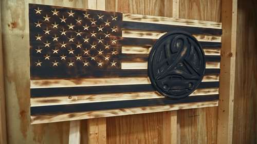
Hope everyone is doing well. Today I want to walk you through a process that I have recently became a tad bit obsessed with. That would be using the CNC to make 3D carvings and engravings. I had a chance to make a good friend of mine a flag for the waiting area of if automotive tint and detailing business. I wanted to add a special twist to the flag and decided the best way to do this was to add a 3D carving of his business logo to the flag. It was a lot of fun to make and the end process to me looked amazing. So I wanted to share the process of how I make the logo and flag and how I set up the toolpaths in Vetric Aspire.
The first thing I had to do was to determine an set up the material setup in Aspire. (Tip: When opening new project in Aspire hold down the shift and ctrl keys to allow you to access the maximum resolution setting). For this particular flag the material size will be 16 by 30 inches. The panel I will be using is 1 inch in thickness. When setting up your job and material on aspire for any kind of 3d cutting I prefer to us the machine bed as the Z axis zero as well as the X and Y Datum zero in the lower left hand corner.
I use this method for a couple of different reasons. First the Z axis zero being set to the machine bed will allow for you to change bits for any reason during the cutting process or if needed for the next tool path. When making 3D toolpaths and cuts you usually do not have a full height surface area to use for a material based Z axis Zero.
On my cnc I have set up the machine to have a constant X and Y zero point where no matter what I am cutting it will align with the lower left hand corner of the material every time. This makes for doing multiple stage cuts much easier and more accurate.
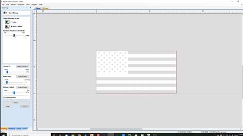
With your job an material setup complete you can start with designing the flag. While you may want or need to design your flag from nothing I have found it is quick to use a jpeg black and white image of a flag to make a bitmap to speed up the design process. The one catch to this is that you exact sizes of your stars and stripes will determined by the size of the flag you are making. Using a bitmap trace to make the flag also allows you to adjust the sizing of your flag as one group.
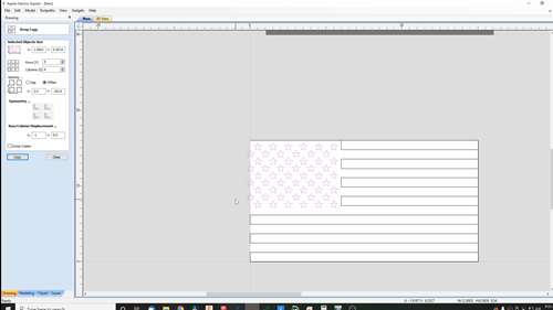
To make the flag simply drag the flag jpeg onto the work area and then resize it to fit your material or to fit your desired specifications. Then click the Trace bitmap icon ( the one that looks like a bird) to then adjust the threshold settings as desired and press apply. You may also adjust some of the other setting to get a smooth prefect outline of the flag. The higher quality the flag being traced is the better the bitmap will be. Using a vector of the flag is best as the edges are not jagged due to pixel dilation caused when you enlarge the image. For my flag I did not like how the stars were looking after the bitmap was created so I decided to create new stars.
I started by opening the star tool and then finding the center of the first star on the flag. The courser will snap to the center of the star when it is close to the center of the star. Then click and drag the star to match the size of the stars from the bitmap. Once the bitmap is ungrouped to it original layers by right clicking the bitmap and clicking ungroup you will be able to remove all of the stars on the flag created by the trace bit map. Once you have done this you can then use the array tool to crate all of your stars. The stars should be spaced evenly with an offset of every other row.
I am not giving exact measurements just due to the measurements you will need will be different depending on the size of the flag you are making. Offset the rows of stars by the same amount of the size of the star. This will but the stars in a perfect diagonal pattern. ( Keep in mind this in not a perfect proportional flag that I am building there are online tools to help you find the exact spacing and sizing of each component for different size flags).
Once the stars are complete I then move them onto there own layer and then repeat this process with the stripes. This is done by selection all of the stars and right clicking on them then choose the move to layer tab in the drop-down menu. I like to create a new layer for each of the components allowing you to turn them on and off when needed.
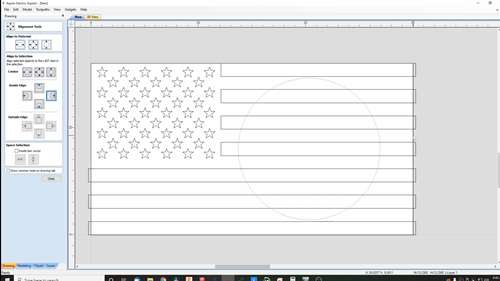
With the components of the flag completed I then created what would become the pocket for the logo. The logo itself would me be made as a separate file and cut from a piece of ¾ inch mdf. So the pocket if important for proper placement of the logo as well as give the flag a clean look. You will first have to determine the size you are going to make your logo. I wanted the logo close to 13inches in total with the boarders after it is placed into the flag.
So I started off with a 13 inch circle crated using the circle tool. Crating the circle with a diameter of 13 inches. To align the circle I first used the alignment tool to position the circle in the center of my material on the Y axis. Once this is done I drew a rectangle around the perimeter of the material surface. The material surface was used for this not the flag as the flag would take the entirety of the material and the circle and logo would need to be centered as such. Once the rectangle has been created select the circle first then holding the shift key the rectangle and click the align to inside right in the alignment tool.
This will align the edge of the circle to inside edge of the rectangle. The circle should be centered between the inner edge of the stripes and the outer edge of the material. To find this distance measure using the measurements tool the distance between those two point and subtract the size of the circle then divide by 2. This will tell you distance you need to move the circle toward the stars to perfectly center it on the stripes. You can then move the circle using the move tool.
To then remove the stripes within the circle I selected all of the stripes within the circle and while holding the shift key selected the circle its self. Then using the trim tool remove the vectors within the circle. Not only will this remove the vectors quickly but it will also rejoin the stripes to them selves leaving no open vectors to repair.
I then offset the circle by ¼ of an inch inwards to allow for the secondary border on the flag as well as giving the vector that would be used to create the pocket for the logo.
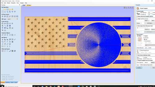
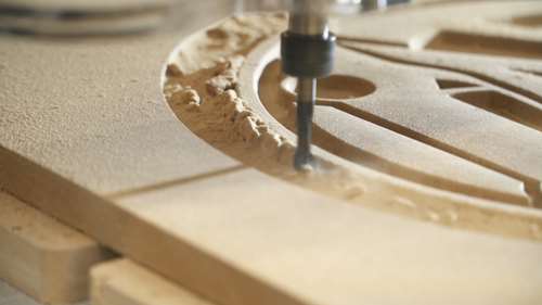
Now the body of the flag is complete and I could move on to settting up the tool paths. For the stars I would be doing a v-carve toolpath using a 90 deg vee bit from bitsbitgscompany.com. Running at a spindle speed of 18000 Rpm and a feed rate of 80 inches/min. The stripes and the logo pocket would be cut using a ¼ in endmill downcut bit. The endmill spindle speed would be 17000 rpm and a feed rate of 100 in/min and a maximum depth cut of 1/8th of an inch. These toolpaths can then be saved as cuts one and two. I also label the toolpaths with the size of the bit that will be needed for that particular cut.
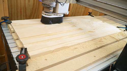
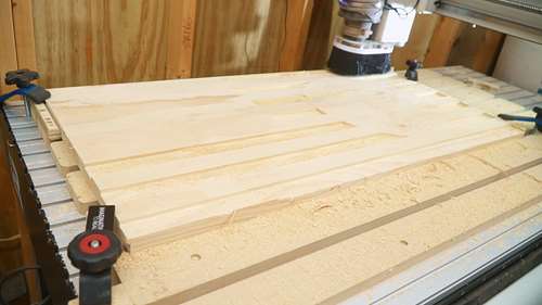
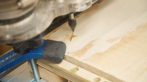
Now I went ahead and cut the flag from the panel I had previously made. Make sure the panel is held securely and will not move during the cuts. After the flag as been cut check over all of the cuts to ensure that everything is as it should be before moving on to crating the 3d logo.
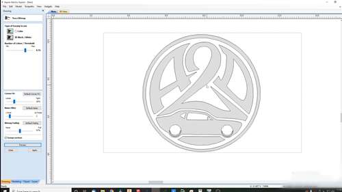
The creation starts off with opening aspire the same way that was done for the flag. The difference this time will be in the material size alone all of the other setting will be exactly the same. For the logo I would be using ¾ inch Mdf cut to a 16 by 16 inch square. With all of the material setup done I then followed the same steps for tracing the bitmap of the logo. Once I had the workable vectors I then could then resize them to 12.74 inches. This would allow for a small amount of tolerance to allow a tight fit into the logo pocket but not so much causing fit issues. After sizing the logo I then centered it on the material using the alignment tool.
I could now move on to now setting up the 3D cuts and toolpaths. I started by first reverting the logo to there original layers. Then using the offset tool adding a second circle ½ inch from the outermost circle of the logo. I then used the rectangle tool to create a rectangle bordering the edge of the material surface. This rectangle will become the base of the 3D toolpath.
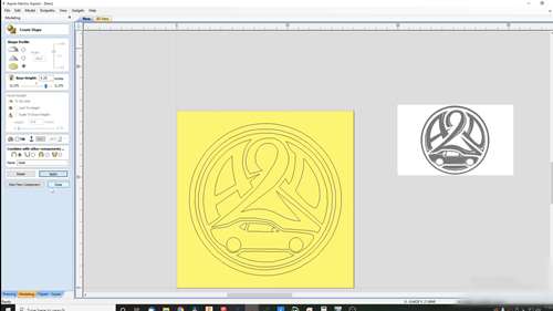
With all of the components now in place I then moved to the modeling tab. First The base would need to be crated. Selecting the rectangle the I made bordering the material edge I then set the base height as .25 inches flat and added to the previous layer. Lable this as base then click apply and then create new component. This might take a little bit of time depending on you computer but this is due to the maximum resolution setting we applied in the start. Next I selected the two circular vectors that outlined the logo. NOT THE OUTTER MOST CIRCLE I CREATED! This border would be the outter edge of the logo and would be added to the previous layer and have a base height of .25 inches as well. But for the profile it would be a circular profile using a 34.2 degree rounded top. This would give the logo a nice smooth bubble top look. Label this component border then click apply and then crate new component,
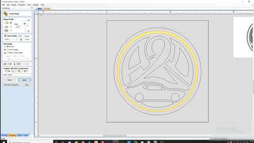
The step is followed to create the logo design but with the design itself selected. The logo itsself will would also be cut using a circular profile at 34.2 degrees and a base height of .25 inches. Just like with the other components label the component as logo and then click apply. As the 3d vectors are created they will turn yellow in the 2D view. You may also click on the 3d view tab at anytime during this process to see how the carving will look and to ensure that the logo is positioned correctly as well as that there are no problems with the vectors.
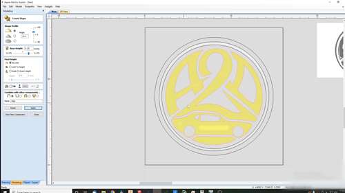
If you are happy with the 3d model at this point you can do as I did and apply a draft. A draft will apply a slight bevel to models edges and make the walls of the vectors less vertical giving them a softer appearance. For this model I used a 10 degree draft but you can experiment with a sharper draft to achieve the look you would like.
Once the draft is complete if you are satisfied with the look of the model select all of the components together. Then duplicate them. Once all of the components have been duplicated crate a new layer and move the duplicated components to the new layer. Un-check the original layer to turn it off. Working with layer 2 add a smoothing filter using the smoothing filter tool. This will smooth out the model and ensure a clean finish. This process will bake the different components into one. This is one of major reasons for moving the duplicate components onto another layer allowing for the originals to stay unchanged if needed later on.
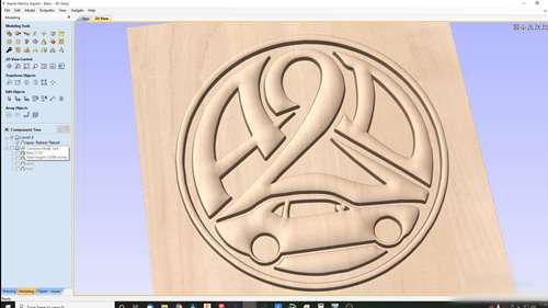
Check over the 3d model closely to ensure that the model looks exactly how you would like it to look. Make sure none of the components are overlapping where not needed. Also make sure the drafts and bevels appear as they should. If you would like to or need to make any changes now would be the time before moving on to creating the toolpaths.
For this portion of the flag there will be a few different toolpaths. First you can run a roughing tool path to remove excess material from the carving using a larger bit. This however is not always necessary. I have now done multiple 3D carvings using only the finishing toolpath. This will save on some time for the entire project as it is one less cut to make. I did however make a roughing pass on this model only to show the effects. Especially with a material like mdf I would only normally do a finishing toolpath alone. One thing to keep in mind is the placement of the model within the material this can be changed id needed in the material set up tab found at the top of the toolpaths tab.
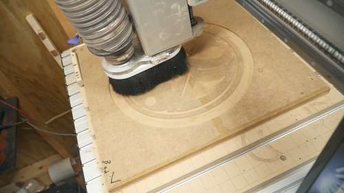
I make my roughing cuts usually with a ¼ inch end-mill but will also use a 1/8 inch if I must. But as mentioned before you do not have to use a roughing pass. For the finishing tool path I use a .0625 inch ball nose bit at 18000 rpm and a 80 in/min feed rate and a step over of 40 percent. This gives the model a clean finished cut with very little sanding needed if any.
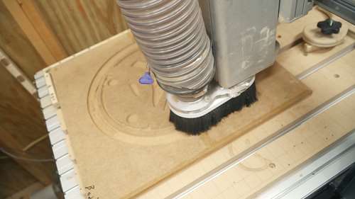
After setting up the 3d passed I then set up the profile cutout of the logo. This is the final tool path that will cut out the logo insert for the flag. This profile is on the outer most vector of the border of the logo. The toolpath is also set to cut on the outside of the line to ensure the correct sizing of the logo insert. I also do not use tabs for this as with mdf there are no need for the tabs on the final pass. Once all of the tool paths are created preview them in the 3d view to ensure all of the cuts preform as they should.
Save the toolpaths by the same process as before and then move on to cutting the carving. This is a process that does take some time and be prepared for the machine to be running a good bit longer that with other cuts.
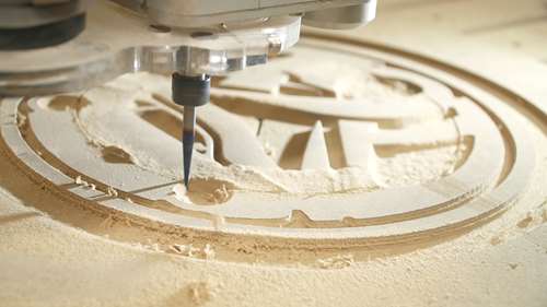
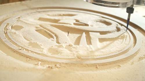
After the carving was finished and cleaned up I then sprayed it black and would be using some sand paper to distress it after installing it into the flag pocket.
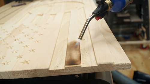
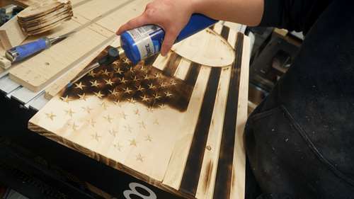
For the flag itself I did a sugi-ban style finish this was done with a torch making the proud stripes completely black and the carved strips lightly colored for contrast and the starts were left open while burning the area around the stars to a black color. I then test fit the logo and made any adjustments needed to get a tight fit.
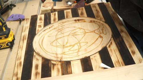
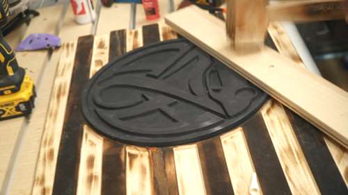
To install the logo I used some Starbond Adhesives Thick Ca Glue and tapped the logo into place with a mallet. This would hold the logo. I also added a backer plate with two key hole slot spaced 16 inches apart on center. This would make hanging the flag easy and accurate.
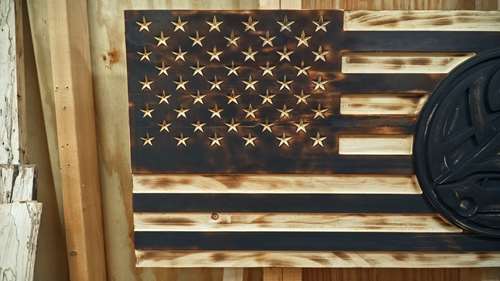
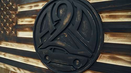
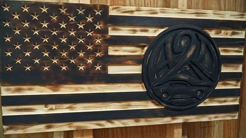
I hope you have found this to be a helpful tutorial. I know the video is a bit long but I did not want to skip out on any details.
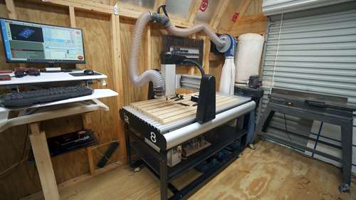
I want to say thank you to i2rcnc.com for sponsoring the video and if you are in the market for an awesome cnc machine go check them out and let them know I sent you. The machines are great and they have awesome customer service. The UCCNC controller is great also allowing you to access and control any aspect of the machine. Go check them out.
Make sure you Subscribe on Youtube to Jpayne Woodworking and for more photos and videos follow me at @jpaynewoodworking. Thank you for watching and if you want to show your support and help me continue to make videos and tutorials like these head over to jpaynewoodworking.com/shop and grab some gear. Thanks again and I will see you on the next one!!
 JPayne Woodworking Creative Craftsmanship